MIPS Single-Cycle Datapath
I am Jyotiprakash, a deeply driven computer systems engineer, software developer, teacher, and philosopher. With a decade of professional experience, I have contributed to various cutting-edge software products in network security, mobile apps, and healthcare software at renowned companies like Oracle, Yahoo, and Epic. My academic journey has taken me to prestigious institutions such as the University of Wisconsin-Madison and BITS Pilani in India, where I consistently ranked among the top of my class.
At my core, I am a computer enthusiast with a profound interest in understanding the intricacies of computer programming. My skills are not limited to application programming in Java; I have also delved deeply into computer hardware, learning about various architectures, low-level assembly programming, Linux kernel implementation, and writing device drivers. The contributions of Linus Torvalds, Ken Thompson, and Dennis Ritchie—who revolutionized the computer industry—inspire me. I believe that real contributions to computer science are made by mastering all levels of abstraction and understanding systems inside out.
In addition to my professional pursuits, I am passionate about teaching and sharing knowledge. I have spent two years as a teaching assistant at UW Madison, where I taught complex concepts in operating systems, computer graphics, and data structures to both graduate and undergraduate students. Currently, I am an assistant professor at KIIT, Bhubaneswar, where I continue to teach computer science to undergraduate and graduate students. I am also working on writing a few free books on systems programming, as I believe in freely sharing knowledge to empower others.
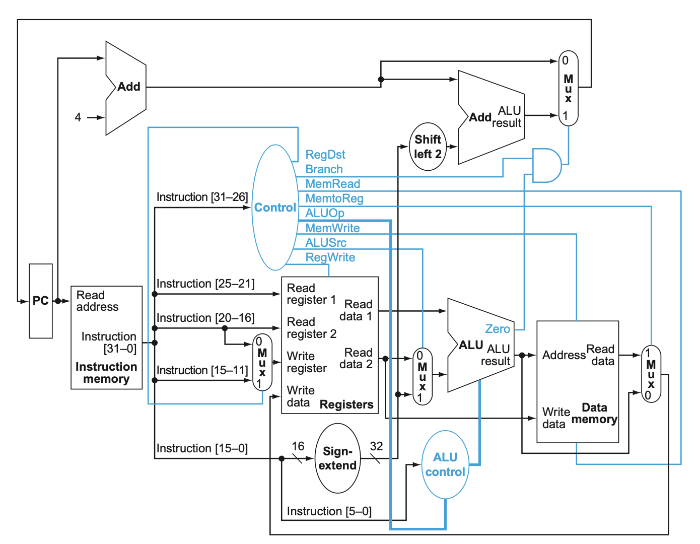
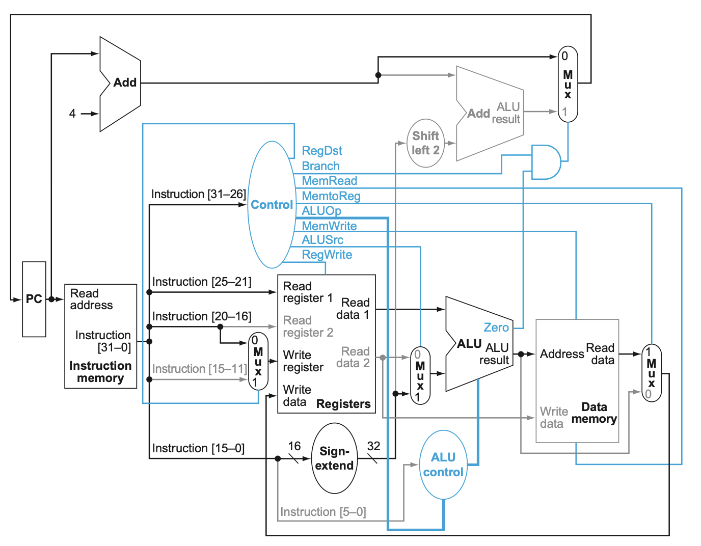
The single-cycle data path for MIPS in the image includes various control signals that govern how the data path components operate during the execution of an instruction. Here's a description of each control signal:
RegDst: This signal controls which register is written to in the register file. If
RegDstis 0, the destination register isrt(field [20-16]). IfRegDstis 1, the destination register isrd(field [15-11]). This is used in instructions likeR-type(e.g.,add, sub) versusI-type(e.g.,lw, sw).Branch: This signal determines whether a branch instruction is being executed. If
Branchis 1 and theZerosignal from the ALU is also 1, it indicates that a branch condition is met, and the PC will be updated to the branch target address. It is used with branch instructions likebeq.MemRead: This signal enables reading from the data memory. If
MemReadis 1, data memory is read during the current clock cycle. This is used forloadinstructions (lw).MemtoReg: This signal controls whether the data to be written to the register file comes from the ALU result or the data memory. If
MemtoRegis 0, the ALU result is written to the register file. IfMemtoRegis 1, data read from memory is written to the register file. It is used for distinguishing betweenlw(load word) andR-typeinstructions.ALUOp: This is a multi-bit control signal that specifies the operation the ALU should perform. The specific ALU operation depends on the instruction type (e.g.,
add, sub, and, or).MemWrite: This signal controls writing to the data memory. If
MemWriteis 1, data is written to the memory location specified by the address input during the current clock cycle. This is used forstoreinstructions (sw).ALUSrc: This signal determines the second operand for the ALU. If
ALUSrcis 0, the second operand is the data read from the second register (Read data 2). IfALUSrcis 1, the second operand is the sign-extended immediate value (used inI-typeinstructions).RegWrite: This signal controls writing to the register file. If
RegWriteis 1, the register file is updated with the result of the operation (either from the ALU result or memory). This is used in instructions that modify registers, such asR-typeinstructions andlw.Zero: This signal is an output from the ALU that indicates if the result of the ALU operation is zero. It is primarily used for the
Branchcontrol logic.Shift left 2: This is not a control signal per se but a shift operation that is applied to the 16-bit immediate field of a branch instruction to calculate the branch target address.
PCSrc (implied by the
BranchandZerosignals): This signal determines the source of the next PC value. If theBranchsignal is active and theZerosignal from the ALU is high, thePCSrcwill select the branch target address; otherwise, it selectsPC + 4.
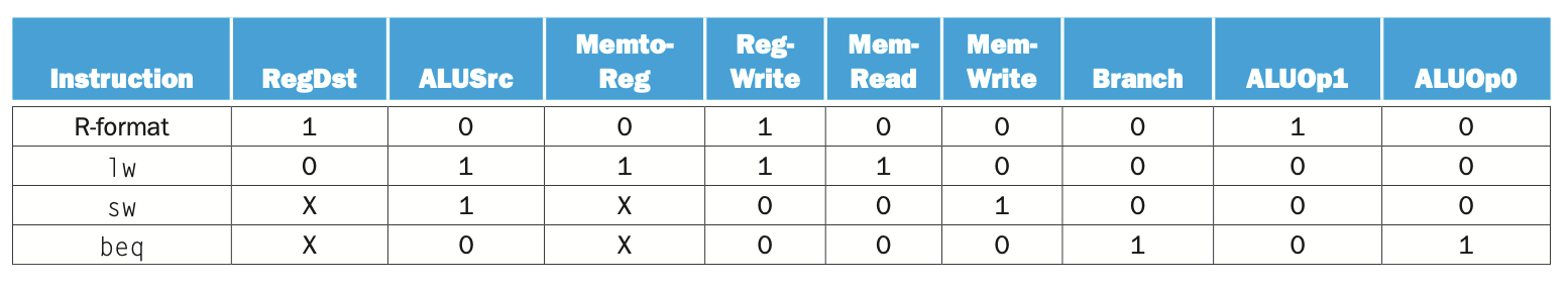
The table provided shows the control signal settings for various MIPS instruction types in the single-cycle data path. This table helps understand how the control signals are configured for different types of instructions to ensure the correct operation of the processor. Let’s go through the table row by row:
1. R-format Instructions (add, sub, and, or, slt)
RegDst:
1- This signal is set to
1for R-format instructions, indicating that the destination register is therdfield (bits [15-11] of the instruction).
- This signal is set to
ALUSrc:
0- For R-format instructions, the second ALU operand comes from the register file (
Read data 2), not from an immediate value. Hence,ALUSrcis set to0.
- For R-format instructions, the second ALU operand comes from the register file (
MemtoReg:
0- Since R-format instructions do not involve memory operations, the value written to the register comes from the ALU result. Thus,
MemtoRegis set to0.
- Since R-format instructions do not involve memory operations, the value written to the register comes from the ALU result. Thus,
RegWrite:
1- R-format instructions write the result back to a register, so
RegWriteis set to1.
- R-format instructions write the result back to a register, so
MemRead:
0- No memory read operation is required for R-format instructions, so
MemReadis0.
- No memory read operation is required for R-format instructions, so
MemWrite:
0- Similarly, there is no memory write operation in R-format instructions, so
MemWriteis0.
- Similarly, there is no memory write operation in R-format instructions, so
Branch:
0- R-format instructions do not involve branching, so the
Branchsignal is set to0.
- R-format instructions do not involve branching, so the
ALUOp:
10- For R-format instructions, the
ALUOpis set to10to indicate that the specific ALU operation is determined by thefunctfield of the instruction. This field provides the details about whether the operation isadd,sub,AND,OR, orslt.
- For R-format instructions, the
2. Load Word (lw)
RegDst:
0- For
lw(load word) instructions, the destination register is thertfield (bits [20-16] of the instruction). Therefore,RegDstis set to0.
- For
ALUSrc:
1lwinstructions use an immediate offset to calculate the memory address, so the second ALU operand should be the sign-extended immediate value. Thus,ALUSrcis1.
MemtoReg:
1- The data loaded from memory must be written to the register file. Hence,
MemtoRegis set to1to indicate that the data to be written to the register file comes from memory.
- The data loaded from memory must be written to the register file. Hence,
RegWrite:
1- The
lwinstruction writes the data fetched from memory into a register, soRegWriteis1.
- The
MemRead:
1- Memory read is required to fetch the data, so
MemReadis set to1.
- Memory read is required to fetch the data, so
MemWrite:
0lwdoes not write to memory; it only reads. Therefore,MemWriteis0.
Branch:
0lwis not a branch instruction, soBranchis0.
ALUOp:
00- For
lwinstructions, the ALU is used to compute the address by performing an addition, soALUOpis set to00(which represents an addition operation).
- For
3. Store Word (sw)
RegDst:
X(Don't care)- For
sw(store word) instructions, there is no destination register for the result. Therefore, theRegDstvalue is a "don't care" (X).
- For
ALUSrc:
1swinstructions also use an immediate offset to calculate the memory address, so the second ALU operand is the sign-extended immediate. Thus,ALUSrcis1.
MemtoReg:
X(Don't care)MemtoRegis irrelevant forswbecause no register is written (RegWriteis0). Therefore, it is marked asX.
RegWrite:
0- The
swinstruction does not write to any register, soRegWriteis0.
- The
MemRead:
0swdoes not require reading from memory, henceMemReadis0.
MemWrite:
1swinvolves writing data to memory, soMemWriteis set to1.
Branch:
0swis not a branch instruction, soBranchis0.
ALUOp:
00- Similar to
lw, the ALU inswinstructions performs an addition to calculate the memory address, henceALUOpis00.
- Similar to
4. Branch on Equal (beq)
RegDst:
X(Don't care)- For
beq(branch if equal) instructions, there is no destination register. Therefore,RegDstis a "don't care" (X).
- For
ALUSrc:
0beqinstructions use two register values to determine equality. Therefore, both ALU operands are taken from registers (Read data 1andRead data 2), settingALUSrcto0.
MemtoReg:
X(Don't care)MemtoRegis irrelevant forbeqbecause no register is written (RegWriteis0), so it is marked asX.
RegWrite:
0- The
beqinstruction does not write to any register, soRegWriteis0.
- The
MemRead:
0beqdoes not involve memory read, henceMemReadis0.
MemWrite:
0beqdoes not involve memory write, soMemWriteis0.
Branch:
1beqis a branch instruction, soBranchis set to1.
ALUOp:
01- For
beqinstructions, the ALU must perform a subtraction to check if the two operands are equal (resultis zero). Thus,ALUOpis set to01.
- For
What does the ALU do and what tells it what to do?
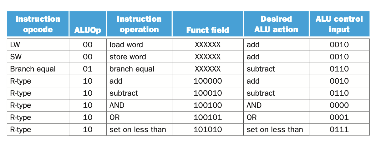
The table provides details about how the ALU (Arithmetic Logic Unit) operates based on different instruction types in a MIPS processor. It outlines the relationship between the instruction opcode, the ALUOp signal from the control unit, the funct field for R-type instructions, the desired ALU operation, and the specific control signals sent to the ALU.
Instruction Opcode:
This is a 6-bit field
[31:26]in the instruction that specifies the basic type of instruction (e.g.,load word,store word,branch equal, orR-typeoperations).The opcode is decoded by the control unit to generate the appropriate control signals, including
ALUOp.
ALUOp:
ALUOpis a 2-bit control signal output by the control unit.It provides a coarse indication of what type of operation the ALU should perform.
ALUOphas three primary settings:00forload word (lw)andstore word (sw)instructions, indicating an addition operation for address calculation.01forbranch equal (beq)instructions, indicating a subtraction operation to check for equality.10forR-typeinstructions, indicating that the specific ALU operation should be determined by thefunctfield ([5:0]).
Instruction Operation:
- This column provides the human-readable description of the instruction (e.g.,
load word,store word,add,subtract).
- This column provides the human-readable description of the instruction (e.g.,
Funct Field:
For
R-typeinstructions, thefunctfield ([5:0]bits of the instruction) provides additional information to specify the exact operation to perform.The
functfield works in conjunction with theALUOpsignal to determine the precise operation of the ALU (e.g.,add,subtract,AND,OR,set on less than).The
functfield is only relevant whenALUOpis10.
Desired ALU Action:
- This column specifies the actual operation that the ALU is expected to perform (e.g.,
add,subtract,AND).
- This column specifies the actual operation that the ALU is expected to perform (e.g.,
ALU Control Input:
This is a 4-bit control signal sent to the ALU to dictate the specific operation to execute.
The ALU Control input is derived from both the
ALUOpand, if applicable, thefunctfield.Different values of the ALU Control input correspond to different operations:
0010foradd0110forsubtract0000forAND0001forOR0111forset on less than
How the ALU is Controlled
Control Unit and ALUOp:
The control unit uses the opcode
[31:26]from the instruction to determine the general type of instruction.Based on this opcode, the control unit sets the
ALUOpsignal:00if the instruction islworsw(requiring an addition to compute memory addresses).01if the instruction isbeq(requiring a subtraction to compare registers).10if the instruction isR-type(using thefunctfield to specify the exact operation).
ALU Control Unit:
The ALU Control unit receives both the
ALUOpfrom the control unit and, if necessary, thefunctfield[5:0]forR-typeinstructions.If
ALUOpis00or01, the ALU Control directly interprets this to set the ALU operation toadd(0010) orsubtract(0110).If
ALUOpis10, the ALU Control examines thefunctfield to determine the specific operation:100000(add) maps to0010.100010(subtract) maps to0110.100100(AND) maps to0000.100101(OR) maps to0001.101010(set on less than) maps to0111.
Examples from the Table
LW (Load Word):
Opcode:
[31:26] = 100011ALUOp = 00(indicating add operation for address calculation)Desired ALU action:
addALU control input:
0010
SW (Store Word):
Opcode:
[31:26] = 101011ALUOp = 00(similar tolwfor address calculation)Desired ALU action:
addALU control input:
0010
Branch Equal (beq):
Opcode:
[31:26] = 000100ALUOp = 01(indicating subtract operation to check equality)Desired ALU action:
subtractALU control input:
0110
R-type (e.g., Add, Subtract, AND, OR, Set on Less Than):
Opcode:
[31:26] = 000000(indicating an R-type instruction)ALUOp = 10(indicating that thefunctfield should determine the operation)Funct field specifies the exact operation (e.g.,
100000for add,100010for subtract)Desired ALU action depends on the
functfield:Add: ALU control input
0010Subtract: ALU control input
0110AND: ALU control input
0000OR: ALU control input
0001Set on less than: ALU control input
0111
R-type (add, etc.)
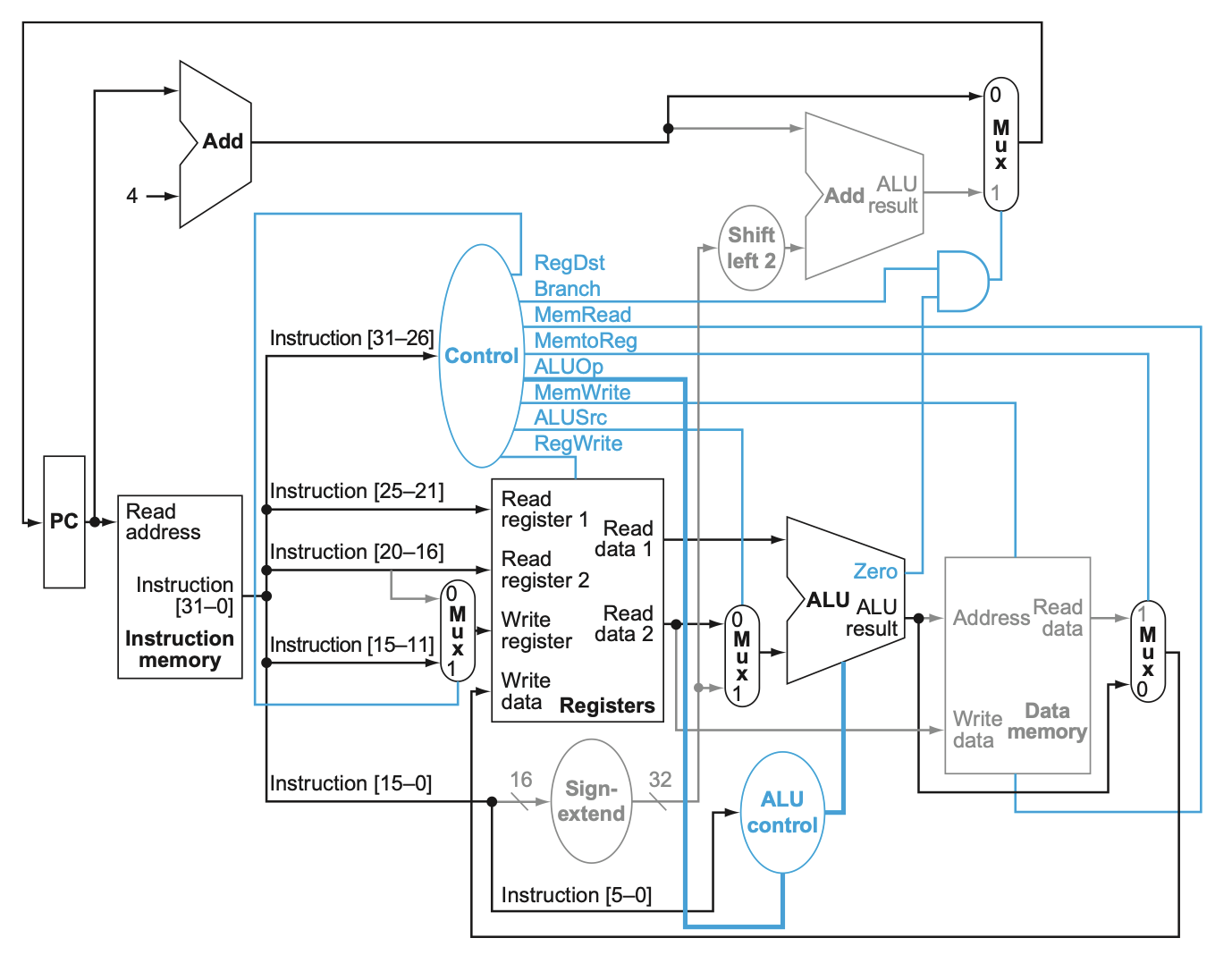
The data path provided is specific to executing R-type instructions (e.g., add, sub, AND, OR, slt) in a MIPS processor.
Step-by-Step Execution of R-type Instructions
Instruction Fetch:
The Program Counter (PC) holds the address of the next instruction to be executed.
The instruction at the address pointed to by the PC is fetched from the Instruction Memory.
The instruction is loaded into the instruction register, and the PC is incremented by 4 to point to the next instruction (since MIPS instructions are 4 bytes).
Instruction Decode:
The fetched instruction is divided into several fields:
op(opcode) is in bits [31-26].rs(source register 1) is in bits [25-21].rt(source register 2) is in bits [20-16].rd(destination register) is in bits [15-11].shamt(shift amount, used in shift instructions) is in bits [10-6].funct(function code for specific R-type operations) is in bits [5-0].
The Control Unit reads the
opfield. For R-type instructions,opis always000000, signaling the Control Unit to set control signals for R-type execution.
Read Registers:
The
rsandrtfields are used as addresses to read two registers (Read register 1andRead register 2) from the Register File.The values stored in these registers are output as
Read data 1andRead data 2.
Execute:
The ALU (Arithmetic Logic Unit) performs the operation specified by the
functfield of the instruction.The ALU Control unit determines the specific operation (
add,sub,AND,OR,slt) based on thefunctfield.ALUSrccontrol signal is set to0for R-type instructions, indicating that the second operand for the ALU comes fromRead data 2(the second register operand), not an immediate value.The ALU receives two inputs:
Read data 1andRead data 2.The ALU performs the desired operation and outputs the result.
Write Back:
The result from the ALU is written back to the register file.
The
RegDstcontrol signal is set to1for R-type instructions, indicating that the destination register (Write register) is determined by therdfield (bits [15-11]).RegWriteis set to1, enabling writing the ALU result back to the register specified byrd.The result of the ALU operation is stored in the register file at the address specified by the
rdfield.
Update Program Counter:
Since R-type instructions are not branch instructions, the next PC is simply
PC + 4, which was already computed during the instruction fetch stage.The MUX that determines the next PC value selects the output that adds 4 to the current PC, as
Branchis0andZerofrom the ALU does not affect the PC.
Control Signals Specific to R-type Instructions:
RegDst = 1: The destination register is determined by the
rdfield.ALUSrc = 0: The second ALU operand comes from the register
rt(Read data 2).MemtoReg = 0: The data to be written to the register comes from the ALU output, not from memory.
RegWrite = 1: Enables writing back to the register file.
MemRead = 0: No read operation from data memory is performed.
MemWrite = 0: No write operation to data memory is performed.
Branch = 0: No branching is performed.
ALUOp = 10: The ALU operation is specified by the
functfield of the instruction.
Load (lw)
The provided data path illustrates the execution of a load word (lw) instruction in a MIPS processor.
Step-by-Step Execution of the lw (Load Word) Instruction
Instruction Fetch:
The Program Counter (PC) contains the address of the instruction to be fetched.
The Instruction Memory reads the instruction located at the address specified by the PC. This instruction is fetched into the instruction register.
The PC is then incremented by 4 (since MIPS instructions are 4 bytes) to point to the next instruction.
Instruction Decode:
The fetched instruction is decoded, and different fields of the instruction are extracted:
op(opcode) is in bits [31-26].rs(base register) is in bits [25-21].rt(destination register) is in bits [20-16].immediate(offset) is in bits [15-0].
The Control Unit reads the
opfield. For thelwinstruction, the opcode is100011, which signals the Control Unit to set control signals accordingly.
Read Registers:
The base register address (
rs) is used to read the content of the source register from the Register File. The data read from the base register (Read data 1) is used as the base address for memory access.The
rtregister is the target register where the loaded data will be written. Although thertregister is specified, it is not read at this stage; rather, it is used later during the write-back stage.
Calculate Memory Address:
The
immediatefield is sign-extended from 16 bits to 32 bits to handle the offset correctly.The ALU performs an addition operation to calculate the effective memory address:
First Operand: The base address obtained from
Read data 1(the content of the base registerrs).Second Operand: The sign-extended immediate value (offset).
The ALUSrc control signal is set to
1forlwinstructions, indicating that the ALU should use the sign-extended immediate value as the second operand.
Memory Access:
The calculated address from the ALU output is used to access the Data Memory.
The MemRead control signal is set to
1to enable reading from data memory.The data at the calculated address is read from the memory and stored in the
Read dataoutput of the Data Memory component.
Write Back:
The data read from the memory is written back to the destination register (
rt).The MemtoReg control signal is set to
1, indicating that the data to be written to the register comes from the memory (not from the ALU result).The RegDst control signal is set to
0, specifying that the destination register is defined by thertfield of the instruction (bits [20-16]).The RegWrite control signal is set to
1to enable writing the data into the register file.The data from the
Read dataoutput of the Data Memory is written into the register specified by thertfield.
Update Program Counter:
As the
lwinstruction is not a branch instruction, the next PC is set toPC + 4.The MUX that controls the next PC value selects the incremented PC (
PC + 4), as theBranchcontrol signal is0.
Control Signals Specific to lw Instructions:
RegDst = 0: The destination register is specified by the
rtfield.ALUSrc = 1: The second operand for the ALU comes from the sign-extended immediate value.
MemtoReg = 1: The data to be written to the register comes from memory (not from the ALU).
RegWrite = 1: Enables writing to the register file.
MemRead = 1: Enables reading from data memory.
MemWrite = 0: No write operation to data memory is performed.
Branch = 0: No branching is performed.
ALUOp = 00: The ALU is set to perform an addition operation to compute the memory address.
Branch on Equal (beq)
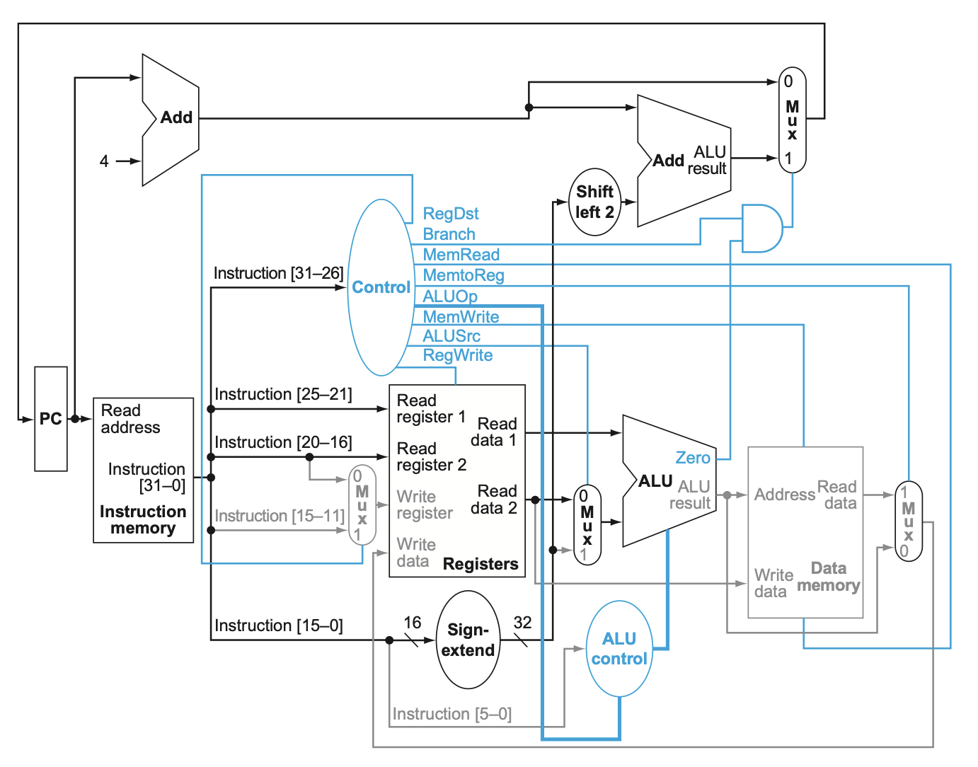
The provided data path illustrates the execution of a branch on equal (beq) instruction in a MIPS processor.
Step-by-Step Execution of the beq (Branch on Equal) Instruction
Instruction Fetch:
The Program Counter (PC) contains the address of the instruction to be executed.
The instruction located at the address specified by the PC is fetched from the Instruction Memory. This instruction is loaded into the instruction register.
Simultaneously, the PC is incremented by 4 to point to the next sequential instruction (since MIPS instructions are 4 bytes long).
Instruction Decode:
The fetched instruction is decoded, and different fields of the instruction are extracted:
op(opcode) is in bits [31-26].rs(first source register) is in bits [25-21].rt(second source register) is in bits [20-16].immediate(branch offset) is in bits [15-0].
The Control Unit reads the
opfield. For thebeqinstruction, the opcode is000100, which signals the Control Unit to set control signals for a branch operation.
Read Registers:
The
rsandrtfields are used to read two registers from the Register File.The data in these registers (
Read data 1andRead data 2) are the two operands that will be compared to determine if the branch should be taken.
Compute Branch Target Address:
The
immediatefield, which represents the offset for the branch, is sign-extended from 16 bits to 32 bits to handle the full address range.The sign-extended immediate value is then shifted left by 2 bits (to account for the 4-byte alignment of instructions) to create the final branch offset.
The branch target address is calculated by adding this shifted offset to the incremented PC (
PC + 4). This addition is performed by an adder separate from the main ALU, depicted as "Add" in the diagram.
Evaluate Branch Condition:
The ALU performs a subtraction operation between
Read data 1andRead data 2to check for equality.The ALU Control signal for
beqis set to perform a subtraction operation (ALUOp = 01).If the result of the subtraction is zero, the
Zerooutput from the ALU is set to 1, indicating that the two operands are equal.
Update Program Counter (PC):
The Branch control signal is set to
1for thebeqinstruction.The
PCSrcsignal is derived from the logical AND of theBranchcontrol signal and theZerosignal from the ALU.If
Zerois 1 (indicating thatRead data 1is equal toRead data 2) andBranchis 1, then thePCSrcsignal becomes 1, causing the PC to be updated to the branch target address calculated earlier.If the branch condition is not met (
Zerois 0), the PC is updated toPC + 4(the next sequential instruction).
Control Signals Specific to beq Instructions:
RegDst = X: Not used in
beqsince there is no register write-back.ALUSrc = 0: Both operands for the ALU come from the register file (
Read data 1andRead data 2).MemtoReg = X: Not used in
beqsince there is no data transfer to a register.RegWrite = 0: No register is written during a
beqinstruction.MemRead = 0: No memory read operation is performed.
MemWrite = 0: No memory write operation is performed.
Branch = 1: Indicates that this is a branch instruction.
ALUOp = 01: The ALU performs a subtraction operation to compare the two registers.
Jump (j)
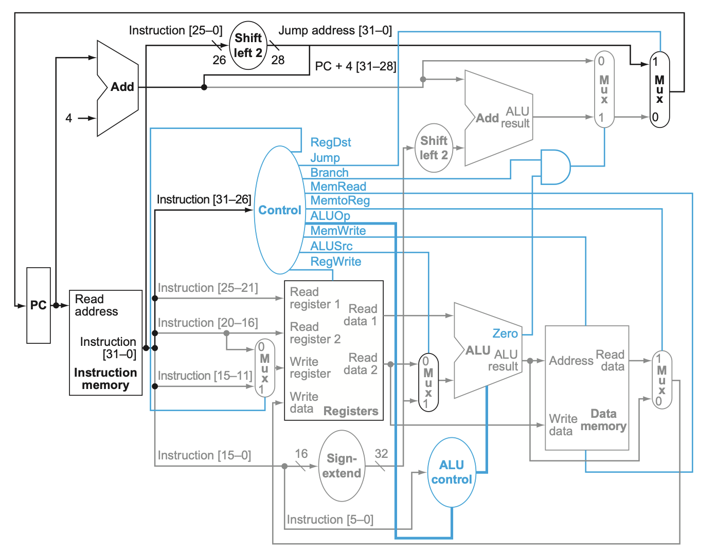
The provided data path illustrates the execution of a jump (j) instruction in a MIPS processor.
Step-by-Step Execution of the j (Jump) Instruction
Instruction Fetch:
The Program Counter (PC) holds the address of the current instruction to be executed.
The instruction at the address specified by the PC is fetched from the Instruction Memory. This instruction is loaded into the instruction register.
Concurrently, the PC is incremented by 4 to point to the next instruction (since each MIPS instruction is 4 bytes long).
Instruction Decode:
The fetched instruction is decoded, and the following fields are extracted:
op(opcode) is in bits [31-26].address(jump target address) is in bits [25-0].
The Control Unit reads the
opfield. For thej(jump) instruction, the opcode is000010, which signals the Control Unit to set control signals accordingly.
Compute Jump Target Address:
The
addressfield, which provides the jump target, is shifted left by 2 bits. This shifting accounts for the 4-byte alignment of instructions in MIPS.The upper 4 bits of the new PC (
PC + 4) are retained (bits [31-28]), while the lower 28 bits are filled with the shiftedaddressfield. This forms the complete 32-bit jump target address (Jump address).
Update Program Counter (PC):
The Jump control signal is set to
1for thejinstruction.The MUX that determines the next value of the PC selects the jump address when the Jump signal is
1.The new PC is thus updated to the calculated jump address, redirecting the flow of control to the target address specified by the jump instruction.
No other operations, such as register or memory read/write, are performed since the
jinstruction only alters the program control flow.
Control Signals Specific to j Instructions:
RegDst = X: Not used in
jsince no register write-back is involved.ALUSrc = X: Not used in
jsince no ALU operation is performed.MemtoReg = X: Not used in
jsince no data transfer to a register occurs.RegWrite = 0: No register is written during a
jinstruction.MemRead = 0: No memory read operation is performed.
MemWrite = 0: No memory write operation is performed.
Branch = 0: Not a branch instruction.
Jump = 1: Indicates that this is a jump instruction.
ALUOp = XX: Irrelevant for
jsince no ALU operation is needed.
Store (sw)
The provided data path illustrates the execution of a store word (sw) instruction in a MIPS processor. Let's go through the execution steps for the sw instruction in detail:
Step-by-Step Execution of the sw (Store Word) Instruction
Instruction Fetch:
The Program Counter (PC) contains the address of the instruction to be fetched.
The Instruction Memory reads the instruction located at the address specified by the PC. This instruction is loaded into the instruction register.
Simultaneously, the PC is incremented by 4 to point to the next sequential instruction (since MIPS instructions are 4 bytes).
Instruction Decode:
The fetched instruction is decoded, and different fields of the instruction are extracted:
op(opcode) is in bits [31-26].rs(base register) is in bits [25-21].rt(source register for data to be stored) is in bits [20-16].immediate(offset) is in bits [15-0].
The Control Unit reads the
opfield. For theswinstruction, the opcode is101011, which signals the Control Unit to set control signals for a store operation.
Read Registers:
The base register address (
rs) is used to read the content of the base register from the Register File. The data read from the base register (Read data 1) is used as the base address for memory access.The
rtregister contains the data that will be stored in memory. The data read from thertregister (Read data 2) will be the data written to the memory.
Calculate Memory Address:
The
immediatefield is sign-extended from 16 bits to 32 bits to handle the offset correctly.The ALU performs an addition operation to calculate the effective memory address:
First Operand: The base address obtained from
Read data 1(the content of the base registerrs).Second Operand: The sign-extended immediate value (offset).
The ALUSrc control signal is set to
1forswinstructions, indicating that the ALU should use the sign-extended immediate value as the second operand.
Memory Access:
The calculated address from the ALU output is used to access the Data Memory.
The MemWrite control signal is set to
1to enable writing to data memory.The data from
Read data 2(the content of thertregister) is written to the calculated memory address.The MemRead control signal is
0since no memory read operation is required.
Write Back:
There is no write-back stage for the
swinstruction because it does not modify any register values.The data path ends after the memory write operation.
Update Program Counter (PC):
As the
swinstruction is not a branch instruction, the next PC is set toPC + 4.The MUX that controls the next PC value selects the incremented PC (
PC + 4), as theBranchcontrol signal is0.
Control Signals Specific to sw Instructions:
RegDst = X: Not used in
swsince there is no register write-back.ALUSrc = 1: The second operand for the ALU comes from the sign-extended immediate value.
MemtoReg = X: Not used in
swsince no data is transferred to a register.RegWrite = 0: No register is written during an
swinstruction.MemRead = 0: No memory read operation is performed.
MemWrite = 1: Enables writing to data memory.
Branch = 0: No branching is performed.
ALUOp = 00: The ALU is set to perform an addition operation to compute the memory address.